Products >> VLSI
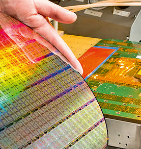
VLSI - Integrates physical layout, verification & translation tools
MYCAD - MyChip Station
- ✧Intorduction
- ✧Layout Editor
- ✧Verification
- ✧Data Translator
- ✧MyAnalog Station
- ✧MyLogic Station
- ✧MyVHDL Station
- ✧MyProtor station
- MYCAD - MyChip Station
- Sinfi - Universal VLSI FPGA-CPLD Development kit
- Compact FPGA-CPLD Development kits
- Application Specific Interfacing modules


MyCAD Design Flow

MyChip Station is a sophisticated physical design system, which can turn a Windows based personal computer into a powerful engineering workstation.
The MyCAD tool includes
MyChip Station
MyAnalog Station
MyLogic Station
MyVHDL Station
MyProtor Station
It integrates physical layout, verification and translation tools. Using MyChip Station, custom layout will be more accelerated with easy-to use polygon layout feature, highest accuracy verification and compatibility with other tools in a hierarchical design environment.
- ✧LayEd : IC, MEMS, FPD Layout Editor
- ✧MyDRC : Hierarchical Design Rule Checker
- ✧LayNet : Hierarchical SPICE Netlist Extractor & Electrical Rule Checker (ERC)
- ✧MyLVS : Layout vs. Schematic Netlist Comparator
- ✧CifGDS : CIF / GDSII / DXF Translator
MyAnalog Station
MyAnalog Station V6.3 is the schematic capture with circuit-level simulator solution for circuit design. MyAnalog Station V6.3 enables the efficient circuit design and manipulation of hierarchical structured circuits from analog library subsets that are mostly frequently used device in SPICE and user-defined compositions. Schematics are created in schematic editor interpreting through MySPICE. MySPICE is a circuit simulator based on Berkely SPICE.
MyChip Station Pro is a full custom layout editor and verification solution which boots the design performance usually targeted to analog circuits
MyLogic Station
MyLogic Station V5.1 is the schematic capture with logic-level simulator solution to provide easy to use and cost effective way of making prototypes. MyLogic Station V5.1 enables FPGA design by generating schematic netlist to structural VHDL or EDIF netlist. And it accepts VHDL codes or EDIF to generate the schematic data.
MyVHDL Station
MyVHDL Station V5.1 is a VHDL simulator providing the integrated working environment to develop the VHDL design. In this workspace you can create, edit, compile, simulate and debug. MyVHDL Station has many features to enhance your development of VHDL design.
MyProtor
MyProtor is a FPGA and ASIC prototype systems. There are various kinds of prototype systems in MyProtor: MP1100X / MP3100X.
Design Tool Condition
- ✧MyVHDL Station : VHDL Design & Simulator
- ✧MyLogic Station : Schematic Design & Simulator, EDIF Netlist Generator
- ✧Xilinx ISE WebPACK : VHDL/Verilog/Schematic Design, Implementation & Configuration
- ✧ModelSim Xilinx Edition-II Starter : VHDL/Verilog Simulator, Free Download http://www.xilinx.com
- ✧EEPROM Configuration S/W : MP3100X use iMPACT of Xilinx ISE
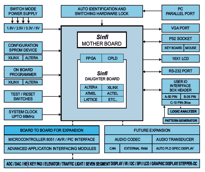
Sinfi : Universal VLSI
FPGA - CPLD development kit
The Board Supports FPGA - CPLD from

Along with Programmable device development boards SiMSteam will supply and support vendor dependend Schematic/VHDL/Verilog/AHDL entry, Simulation, Synthesis, Place & route and Device Programming full suite softwares from Altera, Xilinx, Lattice etc.,
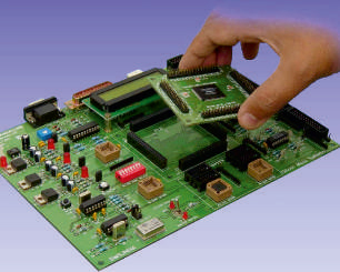
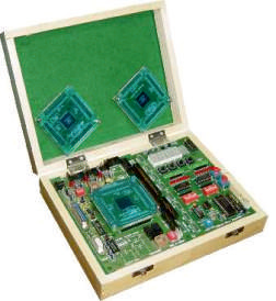
The SiMS Sinfi Board is a unique Universal FPGA -CPLD based development board that allows rapid and interactive implementation and debugging of PLD based designs and has been specially designed to take Vendor independent Programmable devices with a modular architecture in the industry standard factor.
Target programmable FPGA-CPLD devices are housed on plugin fiber transparent glass protected daughter boards, enabling engineers to easily change the target project architecture, providing a truly FPGA -CPLD vendor-independent development board.
For flexible systems design, multiple Sinfi can be chained together to support the development of complex systems comprising of multiple FPGA/CPLD devices spread across multiple PCBs . Connections on the Sinfi Board for userdeveloped boards enables easy porting of designs to SiMS Advanced Application specific Interfacing modules or your own dedicated application
Features :
- ✧Should Supports stand alone or embedded or chain of multiple board operations
- ✧Accommodates 1.8V , 2.5V, 3.3V and 5V standard devices
- ✧Should get Configuration via Re-programmable Flash Serial Read-only, Passive Serial, Joint Test Action Group(JTAG)
- ✧Should have Upto 140 user definable input/outout (IO) pins available, 96 IO line are available for user expansion through header
- ✧Auto device detection and identification facility
- ✧Rich documentation, User's & Technical Reference manual with Architecture, Software tool slides, Datasheets, Example programs in VHDL/ Verilog.
- ✧Technical Specifications :
- ✧Multi frequency compatibility : onboard 4Mhz ,16MHz, 25Mhz up-gradable upto 66MHz.
- ✧Multi Voltage compatibility : onboard for different supply levels generated to match multi volt FPGA/CPLD/EPLD devices (1.8, V2.5V, 3.3V, 5V).
- ✧Multi-Device and Vendor support : FPGA/CPLD/EPLD from Altera, Xilinx, Lattice, Atmel etc., available in TQFP & PLCC package device modules.
- ✧Supports gate density devices.
- ✧Downloading through single parallel port cable fromPC.
- ✧FPGA configuration facility through Flash reprogrammable SPROM.
- ✧Facility to drive the device through external clock frequency
- ✧Power on and Program done LED Indication.
Onboard programmer:
- ✧20pin PLCC type independent sockets provided to program Xilinx and Altera Flash SROM Configuration devices. Versatile on-board Peripherals:
- ✧The Sinfi CVLSI board includes a range of onboard peripheral devices that are accessible from defined pins on the target FPGA/CPLD like.,
- ✧Should be supplied with Spartan 3 FPGA
- ✧Global Reset on board
Communication Connectors:
- ✧The Sinfi CVLSI board should includes a range of dedicated connectors for off board communication & External peripheral for Experimentation on application specific interfacing modules.
General purpose headers
- ✧10Pin FRC connectors – 3Nos
- ✧26Pin FRC connector – 1No.
- ✧50Pin FRC connector – 1No.
GENERAL PURPOSE INTERFACE MODULE
- ✧Combo: Hex keypad, 4 digit seven segment display and 2 Line LCD display
- ✧Combo: Stepper motor, DC motor and relay board
- ✧Combo: ADC / DAC with onboard sensor, voltage, generators
- ✧Logical Input and output interface module
- ✧Downloading through parallel port
Xilinx: FPGA trainer kit with GPIO
Immediately can be supplied and supported devices:
ALTERA:
ACEX1K : FPGA : EPF1K50TC144
APEX 20K: FPGA: EP20K100TC144
MAX3000 : CPLD : EPM3128TC144
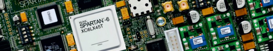
XILINX :
FPGA : SPARTAN-III : XC3S400TQ144
FPGA : SPARTAN-II : XC2S100TQ144
CPLD : COOLRUNNER : XCR3128XLTQ144
CPLD : 9000 : 9572PLCC84
The Board Supports FPGA - CPLD from
FPGA DEVELOPMENT BOARD
Features :
- ✧It Supports stand alone or embedded or chain of multiple board operations
- ✧Accommodates 1.8V , 2.5V, 3.3V and 5V standard any one device
- ✧Configuration via Re-programmable Flash Serial Read-only, Passive Serial, Joint Test Action Group(JTAG)
- ✧Should have 96 IO line are available for user expansion through header
- ✧Rich documentation, User's & Technical Reference manual with Architecture, Datasheets, Example programs.
Technical Specifications :
- ✧Multi frequency compatibility : onboard 4Mhz, up-gradable upto 66MHz.
- ✧Multi Voltage compatibility : onboard for different supply levels generated to match multi volt FPGA/CPLD/EPLD devices (1.8, V2.5V, 3.3V, 5V).
- ✧Multi-Device and Vendor support : FPGA/CPLD/EPLD from Altera, Xilinx, Lattice, Atmel etc., available in TQFP & PLCC package device modules.
- ✧Supports different gate density devices.
- ✧Downloading through single parallel port cable fromPC.
- ✧FPGA configuration facility through Flash reprogrammable SPROM.
- ✧Facility to drive the device through external clock frequency
- ✧Power on and Program done LED Indication.
Onboard programmer :
- ✧20pin PLCC type independent sockets provided to program Xilinx and Altera Flash SROM Configuration devices.
Versatile on-board Peripherals :
- ✧The CVLSI board includes a range of onboard peripheral devices that are accessible from defined pins on the target FPGA/CPLD like.,
- ✧Supplied with defined FPGA or CPLD
- ✧Global Reset on board
Communication Connectors :
- ✧The CVLSI board includes a range of dedicated connectors for off board communication & External peripheral for Experimentation on application specific interfacing modules.
With onboard XILINX : FPGA : SPARTAN-III : XC3S400TQ144 Summary of Spartan-DEVICE: XC3S400 ; System gates: 400K ; Equivalent logic cells: 8064 ; CLB array: Rows: 32, Columns: 28, Total CLBs: 896 ; Distributed RAM Bits: 56K (K=1024) ; Block RAM bits: 288K ; Dedicated Multipliers: 16 ; DCMs: 4 ; Max User IO: 264 ; Maximum Differential IO pairs: 116
With onboard XILINX : SPROM : configurable DEVICE : XC18V01PC20C
General purpose headers:
- ✧10Pin FRC connectors – 3Nos
- ✧26Pin FRC connector – 1No.
- ✧50Pin FRC connector – 1No.
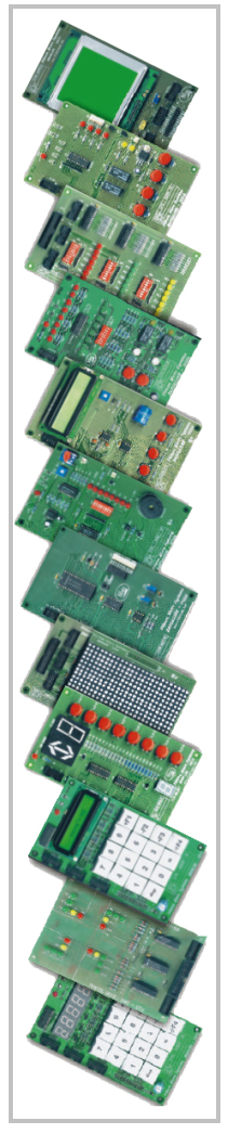
Silicon Application specific interfacing modules are compatible with VLSI - FPGA/CPLD, Embedded development kits based on 8/ 16/ 32 bit microcontrollers and Advanced Microprocessor 8086 based Parallel/USB based modules.
The 10pin and 26pin FRC connectors are provided for compatibility. Each kits will be supplied with 10 or 26 pin FRC cables for interface.
Each Modules are mounted in plastic box. and supplied with users technical reference manual and circuit diagram.
- SiMS-ADCTMP
- Analog to Digital converter
- Teperature control interface module
- 8 bit 8 channel ADC, RTD and Thermistor
- SiMS-DACBUZ
- Digital to Analog & Buzzer
- 8 bit Single channel DAC buzzer
- SiMS-DIORLY
- Logical Input / Output Module
- 8 input and 8 output LED. Two cross over relay
- SiMS-DISHEX
- Seven segment display. Hex Keypad interface
- 6 digits seven segments
- 4x4 switch matrix
- SiMS-LCDHEX
- 16 characters Single Line LCD display
- LCD display with back light
- 4x4 Matrix de-bounce switches
- Hex keypad interface
- SiMS-GENTLC
- Traffic light controller simulator
- Four roads junction simulation
- Vehicle and pedestrians movement
- SiMS-RTCLCD
- Real time Controller with LCD display
- Real time Clock chip programmable
- Read out i2c based & serial EEPROM Interface
- 16 characters x 1 line LCD display
- Display with back-light control
- Facility to define four junction keys
- SiMS-MATDIS
- Matrix Graphics display interface module
- 7x5 Dots display 10Nos framed to get 25x14 dots
- SiMS-GRPDIS
- Graphics LCD display interface
- 128x128 pixels LCD display interface graphical apps
- SiMS-INFRMT
- Infrared Receiver & Transmitter interface
- Standard remote control input
- Potential free relay to explain the application
- SiMS-GENELV
- Elevator operation interface
- Request from inside & outside of elevator simulation
- Movement of elevator through different color LED
- Flexible software to operate in different options
- SiMS-SERIAL
- RS-232 & 485 Communication interface
- To undersand the concept of RS232 & RS485 standards
- 9 pin D type connector provided to interface with PC
- SiMS-STPDCN
- Stepper and DC motor interface
- 0.5Kg/cm2 torque three phase stepper motor interface
- Direction step & speed control
- DC motor speed direction control module 5V/12V DC
- Facility to define four function keys
- SiMS-AUDRT
- Audio Chip Interface
- to understand the concepts of recording
- playback feature with speaker output through controller
Silicon Application specific COMBO interfacing modules are compatible with VLSI - FPGA/CPLD, Embedded development kits based on 8/ 16/ 32 bit microcontrollers and Advanced Microprocessor 8086 based Parallel/USB based modules.
The 10pin and 26pin FRC connectors are provided for compatibility. Each kits will be supplied with 10 or 26 pin FRC cables for interface.
Each Modules are mounted in plastic box or comes with main boards, and supplied with users technical reference manual and circuit diagram.
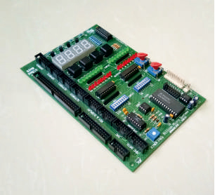
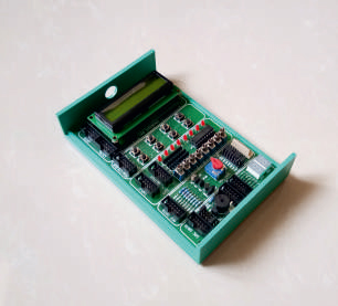
1. SIMS-DAQIO-401A
- ✧4 Digit 7 Segment display
- ✧4 un assigned 4x1 keypad
- ✧16 logical inputs through DIP switch with Green LED indication and 16 logical outputs with RED LED indication
- ✧Analog to Digital converter with internal and external analog signal provisions
- ✧On board Voltage, Frequency, Current signals as reference input for ADC
- ✧Power mate connector provided for external voltage, frequency, current signals as input to ADC.
- ✧Jumper selection provision for external or internal ADC signals
- ✧Single channel Digital to Analog signal converter to generate the wave forms.
- ✧10pin, 26 pin, and 50pin FRC connectors are provided for interface.
- ✧this board can be supplied with FPGA boards or Microcontroller kits in Wooden box.
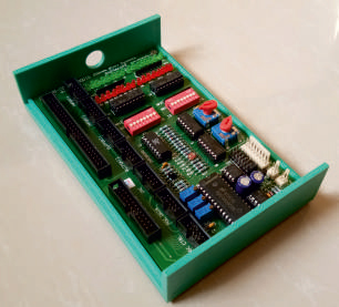
2. SIMS-COMBO-DAQIO
- ✧16 logical inputs through DIP switch with Green LED indication and 16 logical outputs with RED LED indication
- ✧Analog to Digital converter with internal and external analog signal provisions
- ✧On board Voltage, Frequency, Current signals as reference input for ADC
- ✧On board thermister, LDR as sensors
- ✧Power mate connector provided for external voltage, frequency, current signals as input to ADC.
- ✧Jumper selection provision for external or internal ADC signals
- ✧Single channel Digital to Analog signal converter to generate the wave forms.
- ✧10pin, 26 pin, and 50pin FRC connectors are provided for interface.
- ✧Mounted in Plastic box
- ✧
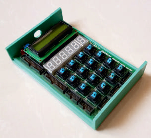
3. SIMS-COMBO-HEXDISP
- ✧16 character x 2 line LCD display with back light, Brightness can be controlled using potentiometer
- ✧6 digit seven segment display
- ✧4 x 4 matrix key board
- ✧10pin & 26 pin FRC connectors are provided for interface.
- ✧Mounted in Plastic box
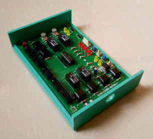
4. SIMS-COMBO-MOTRRLY
- ✧Stepper motor controller driver with four LEDs indication
- ✧motor can be connected through power mate connector
- ✧DC motor controller through relay with two LEDs indication for motor rotation direction
- ✧Two + four un assigned press button keys are provided for key programming
- ✧Two Compact lightweight DPDT contact relay of 5V DC coil voltage; 24V DC contact voltage, 2A contact current provided.
- ✧10pin & 26 pin FRC connectors are provided for interface.
- ✧Mounted in Plastic box
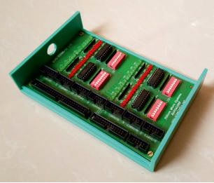
5. SIMS-COMBO-32 I/O
- ✧32 logical inputs through DIP switch and Red color LED indication
- ✧32 logical outputs through Green color LED indication
- ✧10pin, 26 pin, and 50pin FRC connectors are provided for interface.
- ✧Mounted in Plastic box
Silicon Application specific COMBO GPIO interfacing modules are compatible with Embedded development kits based on 8/ 16/ 32 bit microcontrollers or VLSI FPGA-CPLD trainer kits.
The 10pin FRC connectors are provided for compatibility. Each kits will be supplied with 10 FRC cables for interface.
The individual interfacing blocks are isolated, the power drawn from the main controller board.
Each Modules are mounted in plastic box or comes with main boards, and supplied with users technical reference manual and circuit diagram.
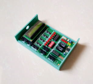
1. SIMS-GPIO-2
- ✧2 Digit 7 Segment display
- ✧8 un assigned 4x3 keypad
- ✧8 logical inputs through DIP switch & 8 logical outputs with Red LED indication
- ✧Analog to Digital converter with internal and external analog signal provisions
-
- ✧On board Voltage signals as reference input for ADC
- ✧Power mate connector provided for external voltage, frequency, current signals as input to ADC.
- ✧Jumper selection provision for external or internal ADC signals
- ✧On board Thermister, LM35 and LDR provided for temperature and light sense
- ✧Single channel Digital to Analog signal converter to generate the wave forms and buzzer provided for tone generation.
- ✧10pin connectors are provided for interface.
2. SIMS-GPIO-3
- ✧8 logical inputs through DIP switch & 8 logical outputs with Red LED indication
- ✧16 Character x 2 line LCD display with backlight
- ✧8 un assigned 4x3 keypad
- ✧Stepper motor controller driver with four LEDs indication
- ✧motor can be connected through power mate connector
- ✧DC motor controller through relay with two LEDs indication for motor rotation direction
- ✧10pin FRC connectors are provided for interface.
- ✧Mounted in Plastic box
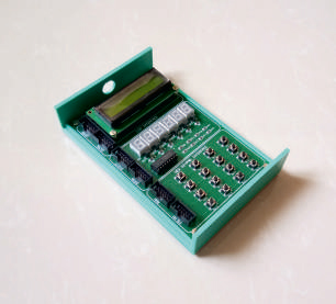
3. SIMS-GPIO-4
- ✧16 character x 2 line LCD display with back light.
- ✧6 digit seven segment display
- ✧4 x 4 matrix key board
- ✧10pin FRC connectors are provided for interface.
- ✧Mounted in Plastic box
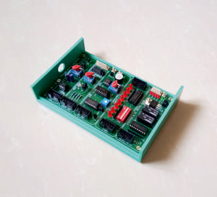
4. SIMS-GPIO-5
- ✧Stepper motor controller driver with four LEDs indication
- ✧motor can be connected through power mate connector
- ✧DC motor controller through relay with two LEDs indication for motor rotation direction
- ✧8 logical inputs through DIP switch & 8 logical outputs with Red LED indication
- ✧External analog input reading through SPI ADC with on board analog reference voltage.
- ✧Single channel Digital to Analog signal converter to generate the wave forms and buzzer provided for tone generation.
- ✧Analog to Digital converter with internal and external analog signal provisions
-
- ✧On board Voltage signals as reference input for ADC
- ✧Power mate connector provided for external voltage, frequency, current signals as input to ADC.
- ✧Jumper selection provision for external or internal ADC signals
- ✧On board Thermister, LM35 and LDR provided for temperature and light sense
- ✧10pin FRC connectors are provided for interface.
- ✧Mounted in Plastic box